Products
Categories
- Home
- FM-1050 Rotameter Calibration Charts
FM-1050 Rotameter Calibration Charts
FM-1050 Reference 150mm Charts
Correction Factors
Rotameter Pressure Correction Factors
Rotameter Temperature Correction Factors
Rotameter Gas Correction Factors
FAQ
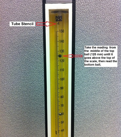
• How do I read the ball in the tube?
Take the reading from the middle of the ball.
• How do I take a reading with two balls in the tube?
Read the top ball until it goes above the top of the chart, then read the lower ball. (The black ball is glass and the silver ball is stainless steel)

• Why are there two balls in the FM-1050 tube?
The flow range of the tube is extended with two balls instead of one.
• What are the units for 0-150 scale on the FM-1050?
The 0-150 scale is in millimeters. Calibration charts for the specific gas and pressure can be found above.
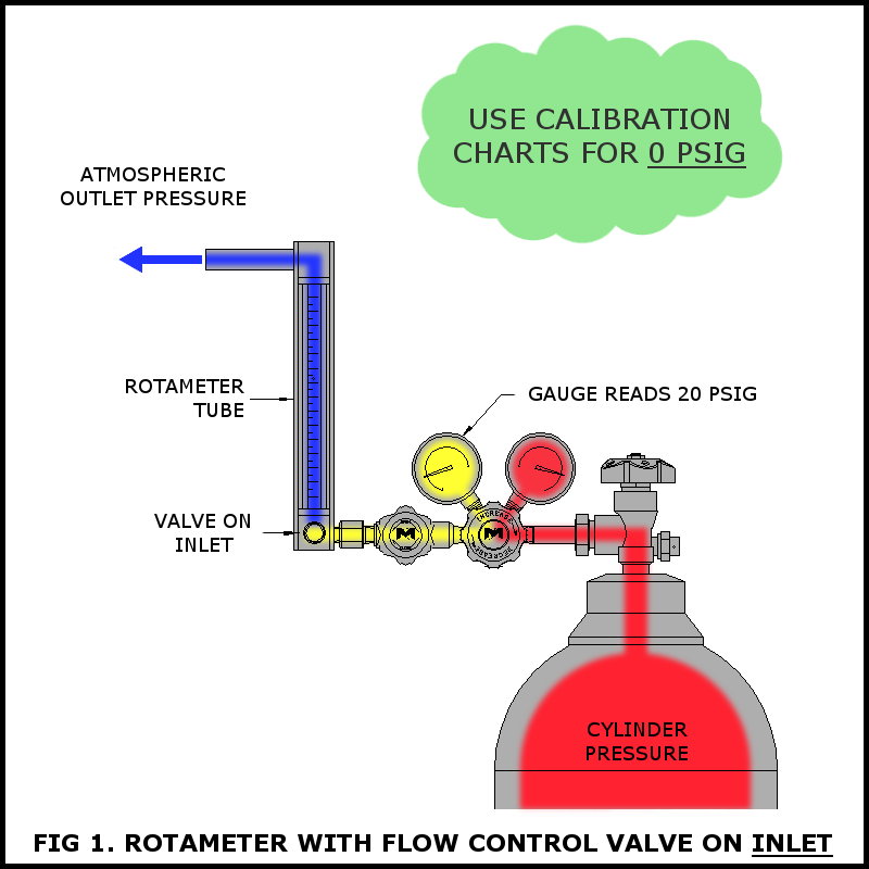
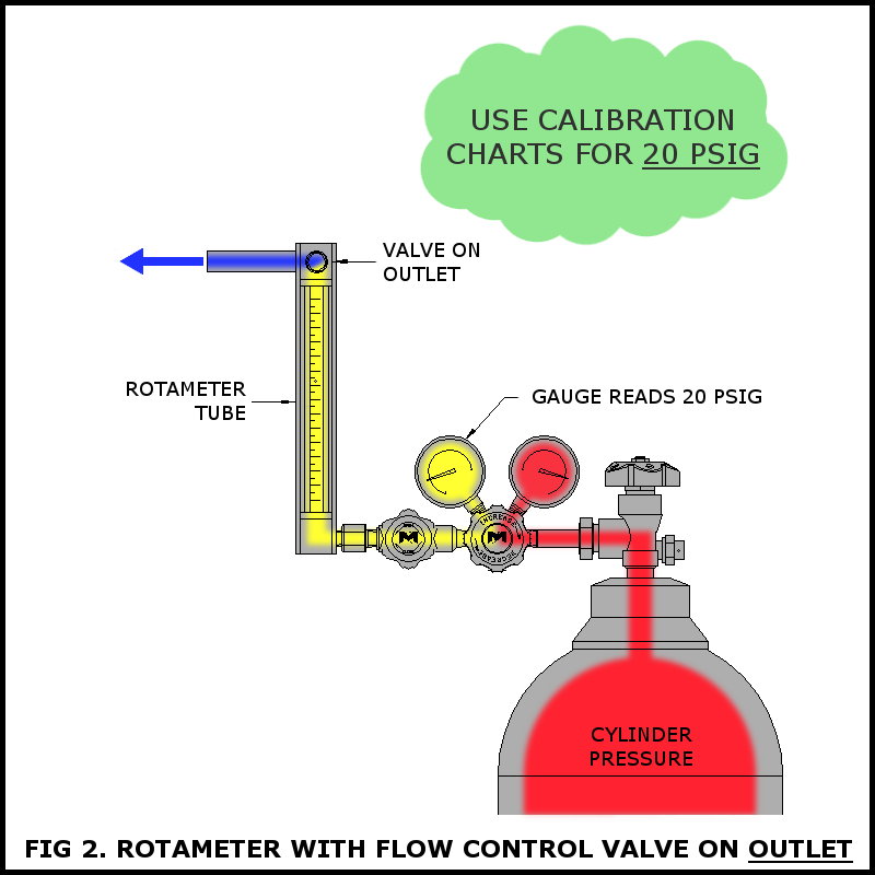
• Why are there different FM-1050 calibration charts for different pressures?
The pressure that you choose is the pressure that is in the tube. Most people have the valve on the inlet and the rotameter flows to an instrument or process at atmospheric pressure so in that case you would use the 0 PSIG charts. Do not use the pressure supplying the rotameter if the valve is on inlet. If your valve is on outlet of the rotameter then either use a pressure correction factor or use a calibration chart corresponding to the pressure in the tube. We have many charts that are for 20 PSIG and 50 PSIG.


 Loading... Please wait...

